

Pengutronix Christmas Tree

PTX Christmas Tree assembly kit
With the outside world getting colder and the days becoming shorter, we at Pengutronix decided to bring a bit of light in these dark days of the year.
Our small crafting project, called PTX Christmas Tree, has thus been created and its template and a short description is available for download.
On this page, we will - in way to many words - guide you through the process of building our little tree.
For instructions you can either watch our video or continue reading.
Preparations
Regarding our template, you will need the following components:
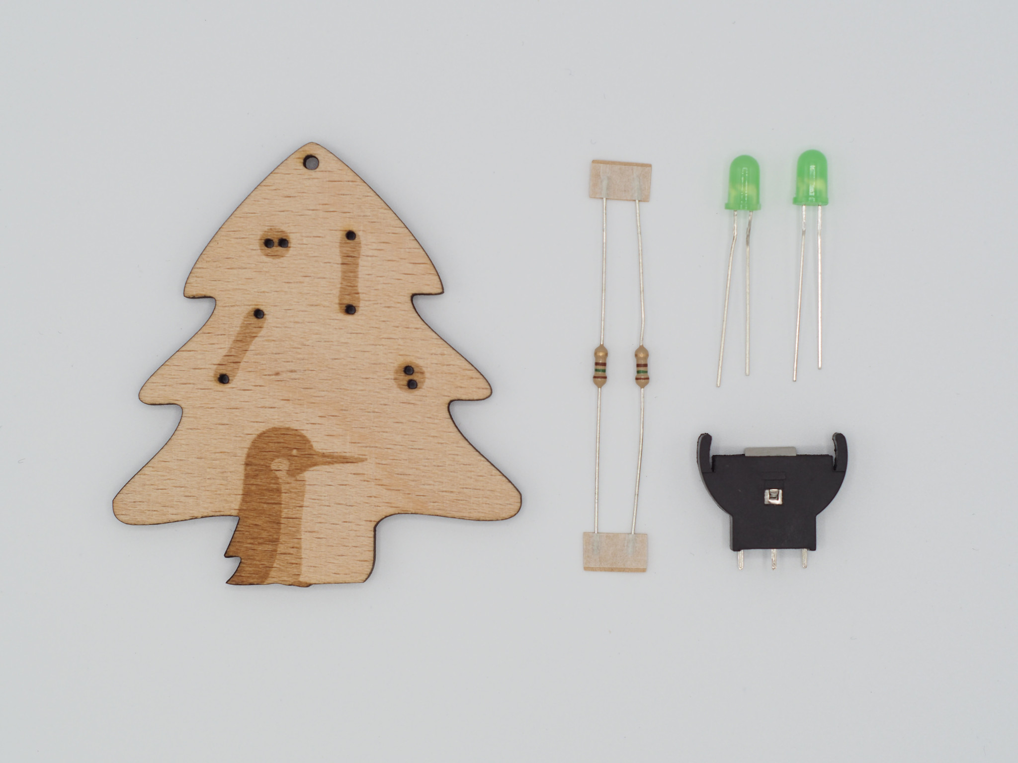
PTX Christmas Tree parts
- 2 LEDs, normal brightness, ⌀ = 5 mm
- 1 socket for CR2032 batteries, contacts at the side
- 1 CR2032 battery at 3 V
We further recommend the following tools:
- soldering iron and solder
- side cutter
- tweezers
- (double-sided) tape
- helping hands (but keep your distance! ;-))
Mental support may be accomplished by providing cookies and hot chocolate; glogg or eggnog should be provided only for later relish.
1st Step: Resistors
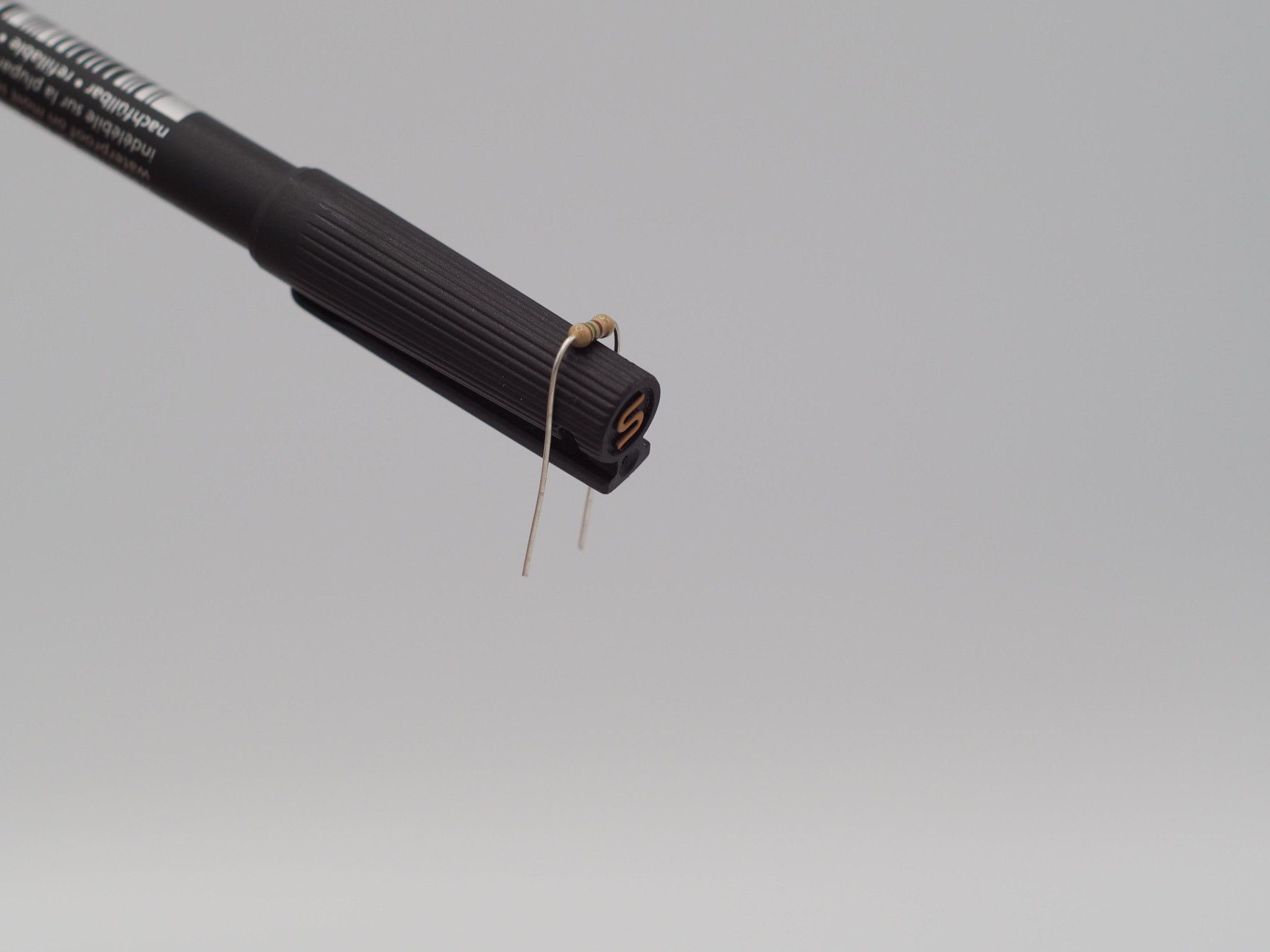
Bend the legs of the resistor

Stick the resistors through the holes

Turn the Christmas Tree
The two resistors have first to be freed from their holding tape by just pulling it straight off. Afterwards, the metal legs have to get in shape in order to fit through the assigned holes in the tree. A pencil of the right diameter might help to bend the legs in a right angle. We can then stick the prepared resistors through the front of our tree.
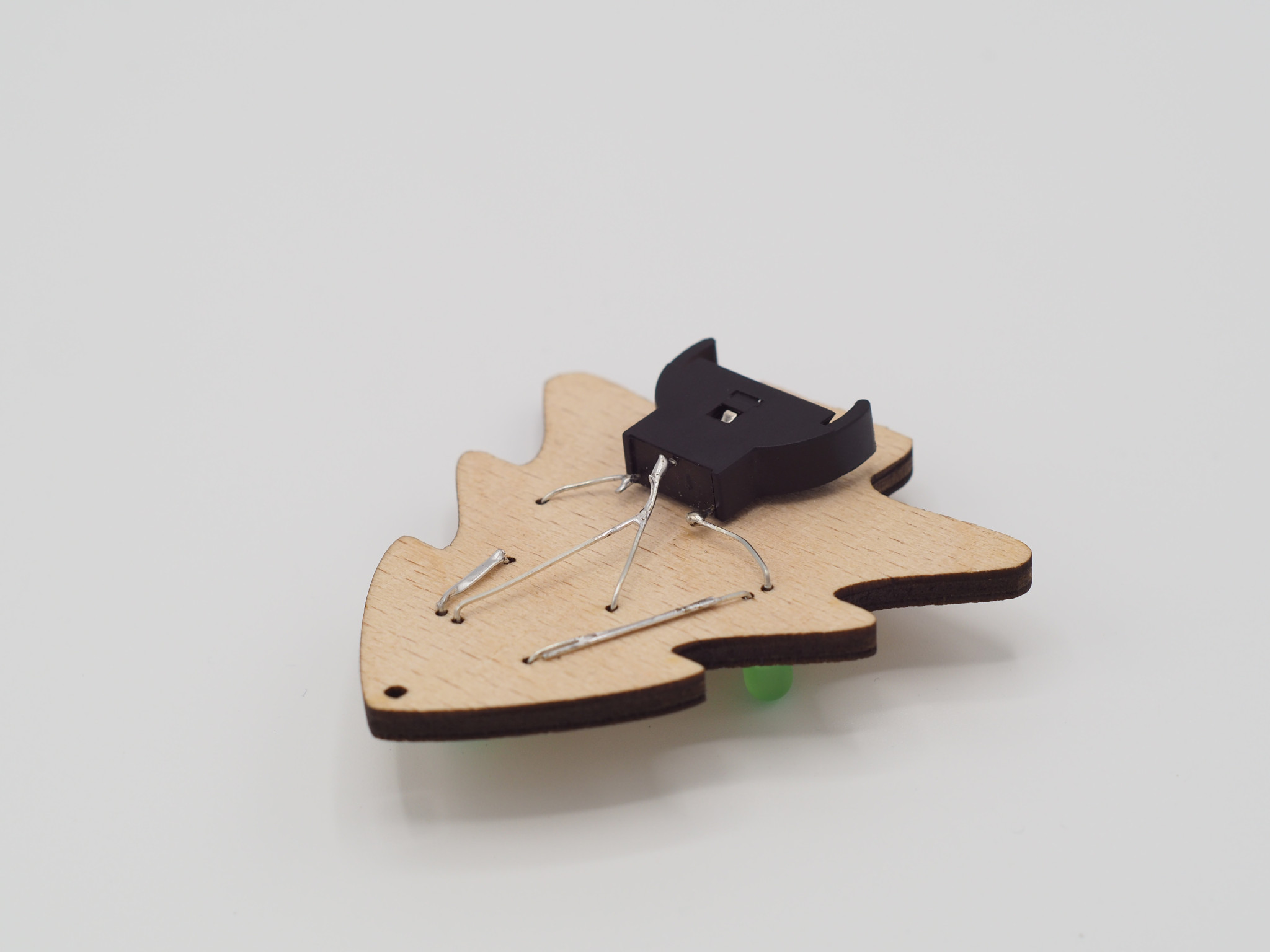
2nd Step: Socket

Attach the socket, by using some double-sided tape

Bend the resistor's leg to the socket

Solder and remove the waste material
We will use the socket as an anchor point for all our components. It is therefore fixed at the backside somewhere at the trunk of the tree using the double-sided tape. Now, for each resistor, we take the leg next to the socket and bend it in its direction. The resistor at the top has thereby to be connected with the sockets minus pol, whereas the other resistor has to be connected to the plus pole.
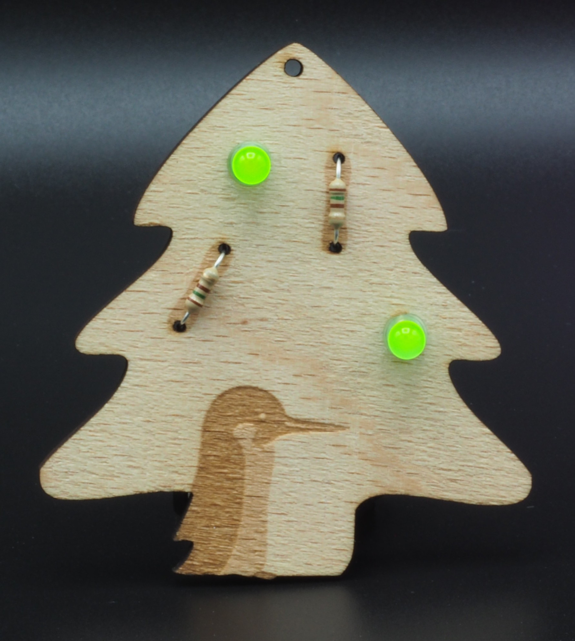
3rd Step: LEDs
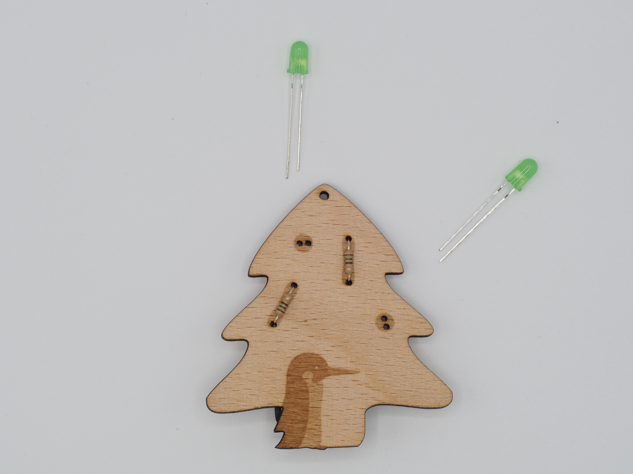
Christmas Tree and LEDs in circuit orientation

Stick the LEDs through the holes

Bend the LEDs legs to the resistors and socket
Solder and remove the waste material
We treat the LEDs like the resistors and stick them right through the holes at the tree's front. Since the LEDs' legs are already in the right shape we do not have to perform any bending right now. However, being semiconductors, the polarity is important. We therefore have to take care that the longer leg (the anode) of the LED at the treetop gets through the left whole, while the longer leg of the other LED has to go through the lower hole.
Now on the back we orient the remaining resistor legs in parallel to their next neighbouring LED legs and establish contact between their surfaces.
The other leg of the LED next to the battery socket has now to be connected to its plus pole. Finally, we can solder the last standing leg of the upper LED to the resistor leg that goes right through the center of our backside.
After having soldered all legs and contacts and removing any remaining excess, we can now insert the battery in its socket.
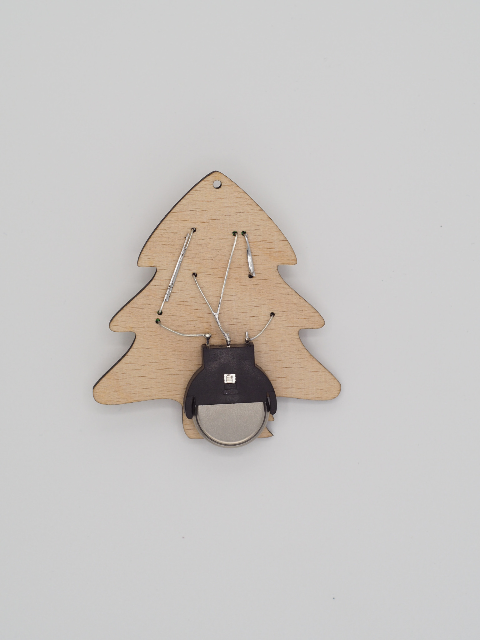
Insert the battery into the socket
Shining PTX Christmas Tree
The remaining hole in the treetop qualifies our resulting little piece of art to be put up in an accommodating scenery.