

eMMC Hardware Partitioning
When designing an embedded system, one must consider both the application and the underlying hardware in combination, if the intended long-term stability is to be achieved. While we discussed the necessity of software updates in previous posts, in this article I describe a way to use a memory subsystem corresponding to its physics to achieve the best retention and lifetime of the whole system.
Retention keeps the ability of the system to boot the application always up to a useful state.
The lifetime is important if the system continuously saves data to the memory subsystem.
Both requirements don't need to conflict. But depending on the application they often do and - more importantly - often do this unnoticed.
eMMC… What?
Internally, an eMMC has a single pool of memory. Unlike its more common sister - the SD card - the eMMC provides external access to the memory pool via so-called hardware partitions.
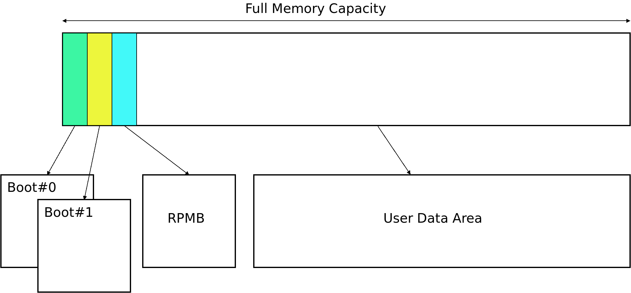
Overview about the hardware partition layout of the memory
The hardware partitions outlined here can be used independently when the Linux system is up and running. The two boot hardware partitions are special and play an important role when the bootloader is started. The CPU can access their content in a simplified manner, which accelerates loading and running a bootloader. Some eMMC devices allow to configure their size as well. The RPMB hardware partitions (RPMB: Replay Protected Memory Block) in turn serve as something completely different, and will be ignored in this article along with the boot hardware partitions. At runtime, only the User Data Area hardware partition (UDA) is used extensively in most systems. And this usage leads to limits for the system requirements from the preamble.
Note: The term hardware partition should not be confused with the otherwise more well known partitions in a partition table (like MBR or GPT), which can be created and managed with the fdisk command. The latter can be used in addition to the hardware partitions.
A Common Scenario
In an embedded system an eMMC is used and both of the two requirements high retention when starting up the system and long lifetime when storing data must be achieved.
At runtime the hardware partitions of the eMMC are visible:
| /dev/mmcblk0boot0 | Boot #0 Hardware Partition |
| /dev/mmcblk0boot1 | Boot #1 Hardware Partition |
| /dev/mmcblk0 | User Data Area Hardware Partition |
Everyone already working with eMMCs knows these device nodes.
First Approach
To achieve the high retention when starting up the system requirement the system starts its bootloader from one of the available boot hardware partitions. After that, the bootloader loads a Linux kernel from the regular UDA hardware partition and the Linux kernel in turn uses a part of the UDA hardware partition as its root filesystem.
To ensure the system can always start up, the developer decides to divide the UDA hardware partition into two parts: The first part should be the read-only mounted root filesystem. The second part should be writeable to be able to store config files and log files or all kind of other data. This partitioning is done with the fdisk command on top of the UDA hardware partition.

First approach to partitioning the UDA hardware partition
This leads to the following visible device nodes of the eMMC device:
| /dev/mmcblk0 | User Data Area Hardware Partition |
| /dev/mmcblk0p1 | Partition for the RootFS, read-only |
| /dev/mmcblk0p2 | Partition for a writeable filesystem |
This approach sounds sensible but during the system's lifetime it still can lead to a bricked system, as to the root filesystem might no longer be readable. The reason is the underlying memory subsystem, which doesn't know anything about this layout and a read-only and a writeable part. It still manages the whole UDA hardware partition as one. Since we are talking about an eMMC device here, we also talking about flash memory as the used technology. And these kind of memories require wear leveling techniques to avoid early failures.
In this context, "wear" refers to many physical effects that arise from repeated writing to the flash blocks. Although the exact causes and effects are quite complex, a simplification is enough for us here: After each additional write cycle, the individual memory cells lose their electrical charge more quickly and at some point can no longer be written. Depending on the NAND technology used, hundreds of thousands (SLC) or only a few thousand (TLC / QLC) cycles can be achieved. In addition to "wear leveling", other techniques are used to deal with these effects. These include: error correction codes (ECC), regular corrections in the background ("scrubbing") and a supply of reserve blocks.
The entire memory area is usually used for wear leveling, since the highest number of write cycles can be achieved in this way. The part actually intended as a read area for the root file system is shifted over time to more heavily used blocks, indicated in the following figure by the circular arrows.

Wear leveling of the whole memory
That's why effects caused by changes in the writeable part can propagate to the part intended for the root filesystem. And that's why neither the lifetime nor the retention of the root filesystem is ensured.
For example, a system that has written a comparatively large amount may no longer be able to accumulated correct errors due to the accelerated loss of charge if it remains switched off for a few months . Thus, neither the desired service life nor the reliability for the root file system is guaranteed.
Better eMMC Partitioning-Based Approaches
Besides the boot hardware partitions, eMMC devices provide additional types of hardware partitions, which are always disabled on delivery and need an additional configuration step to enable. However, as this step cannot be reverted any more, special care and planning should be taken before the actual change. A side effect of enabling hardware partitions is the reduction of the overall capacity of the eMMC. Details about this will follow later on.
The goal of this configuration is to inform the eMMC about its intended use.
To divide the available capacity, an eMMC offers several alternatives:
- Enhanced User Data Area (EUDA)
- General Purpose Partitions (GPPs)
- default
- enhanced
- extended ("system code" or "non-persistent")
It should be noted that the standard does not define the exact meaning of these attributes. Improved reliability is given as an example for the enhanced mode. In addition, it says "The definition of enhanced storage media should be decided upon by each system manufacturer, and is outside the scope of this standard." In practice, enhanced often means that an SLC mode is used. Ultimately, however, it depends on the respective manufacturer of the eMMC, so it is worthwhile to study the relevant documentation.
Enhanced User Data Area
The EUDA leads into an internal change how to manage a part of the UDA. From the user's point of view nothing else changes (except possibly the reduced capacity).
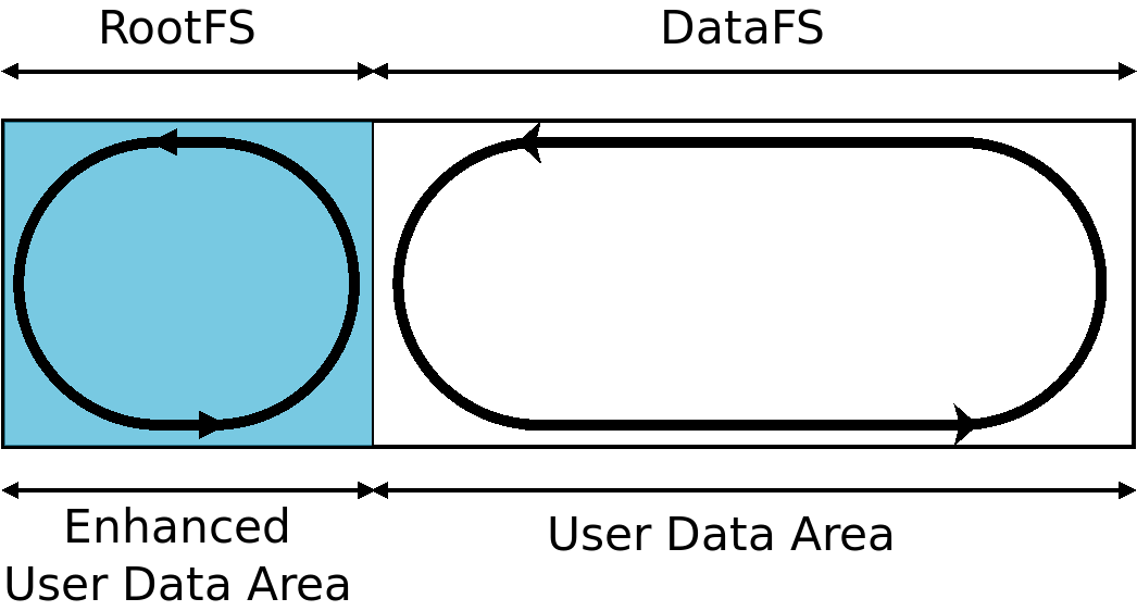
Configuring an EUDA part
From now, not only from the application's point of view, but also from the eMMC point of view these two parts are separated and the eMMC manages both parts differently. Since there is no noticeable change from the user's point of view, it is important to align the filesystem's partitions according to the sizes of both parts via fdisk.
As mentioned before, there is no visible change when an EUDA is configured:
| /dev/mmcblk0 | User Data Area Hardware Partition |
| /dev/mmcblk0p1 | Partition for the RootFS, read-only (covers the EUDA) |
| /dev/mmcblk0p2 | Partition for a writeable filesystem (UDA) |
For any given eMMC model, whether the wear leveling actually manages UDA and EUDA separately, as indicated in the picture, can only be answered with the appropriate documentation.
General Purpose Partitions
In contrast to an Enhanced User Data Area, configuring a General Purpose Partition leads to cutting off some of the UDA memory and offering it as an additional externally visible device. When creating the GPP, you can choose between the default or enhanced storage modes. The meaning of enhanced does not have to be identical for UDA and GPPs.
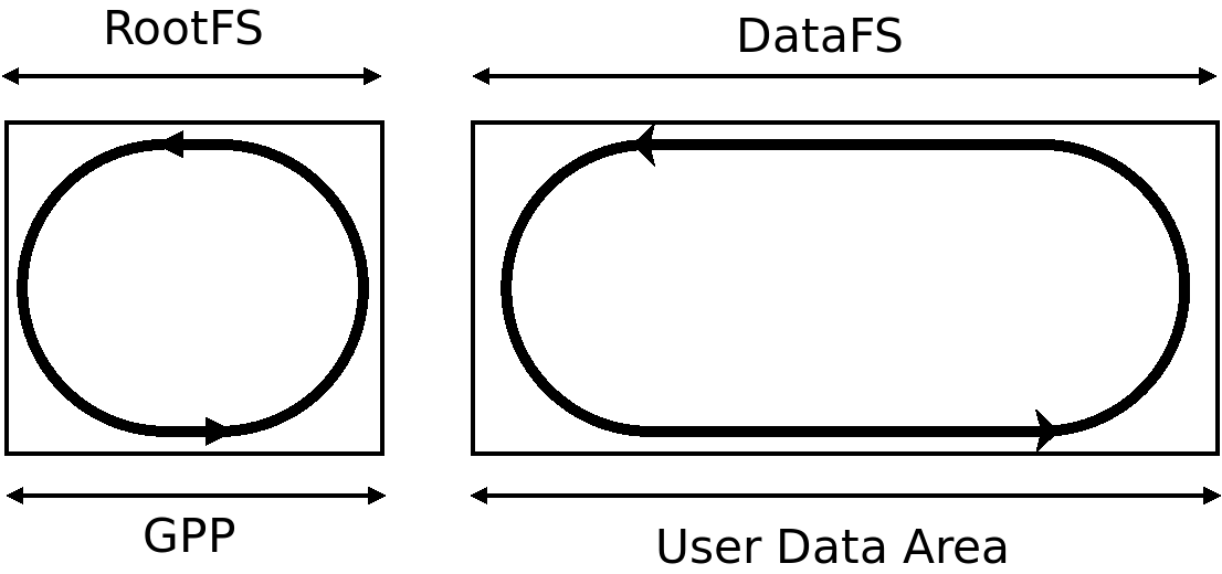
Configuring a GPP
| /dev/mmcblk0gpp0 | GPP #0 Hardware Partition |
| /dev/mmcblk0 | User Data Area Hardware Partition |
At this point support from the application is required in order to make use of the GPP. The bootloaders barebox and U-Boot and the Linux kernel both have this support already.
Under Linux, the GPP as /dev/mmcblk0gpp0 is now a separate device and the eMMC manages it independently from the UDA (which remains accessible as /dev/mmcblk0). It makes no difference which one used. The GPP as well can now be partitioned and formatted. Finally, at runtime the following list of device nodes will exist:
| /dev/mmcblk0gpp0 | GPP #0 Hardware Partition |
| /dev/mmcblk0gpp0p1 | Partition for the RootFS, read-only |
| /dev/mmcblk0 | User Data Area Hardware Partition |
| /dev/mmcblk0p1 | Partition for a writeable filesystem |
Besides the configuration of its internal memory, the eMMC offers some more options to specify the future use of each of the memory parts. This allows the eMMC to adapt its strategy to manage its internal memory more closely to the expected usage.
More about this in a future blog post.
Further Readings

Static Filesystem
Whenever it is a requirement to be able to switch off an embedded device without any previous preparation, the next question is about the consistence of the used filesystem. If this filesystem is used to be written with new content and this new/changed data hasn't done it's way to the persistent media when the power is cut, this new/changed data is lost.

PTXdist: Did you know? Today: Just a reboot
While the development on an embedded system I need to reboot it quite often. Doing so I appreciate to keep the required steps as less as possible and be sure the embedded system uses the recently changed data in a consistent manner.

Pengutronix Recent Open Source Contributions - Linux 7.1 Edition
A tour trough Pengutronix' contributions to Linux 7.1, and to other open source projects
Pengutronix Recent Open Source Contributions - Linux 7.0 Edition
Let's take the Linux 7.0 release as an occasion to look at the Open Source code we've contributed to various upstreams in the last two months.
Pengutronix Recent Open Source Contributions
Let's take the Linux 6.19 release as an occasion to look at the Open Source code we've contributed to various upstreams in the last three months.
Comprehensive RAUC Documentation Update
As in many projects, also in RAUC phases of extensive development did often not leave sufficient time to explain the latest changes, new features or at least some basic concepts in an appropriate manner.